Search This Blog

Saturday, November 6, 2021

An EMC Non-compliant LED Strip

AC9LF's Findings with a FCC and CE labeled product I purchased on Amazon recently.

Here's a link to a similar product. The original that I bought seems to be missing. This one appears to have the same power supply.


I sent inquiries to the seller about this issue with no response after several days so I sent a product review in with my concerns today. (They did eventually respond but only offered to send a replacement. This of course will not work since it is a problem with the product not the individual part. They need to use a real tested and compliant power supply.)

To save my wrists I will paste the review I sent in below and attach the associated images.

-------

I purchased two of these LED light strips one for my wife for Christmas and one for my brother-in-law who is also my neighbor. I didn't realize however when I was buying this that I was also buying a problem. Don't get me wrong, the lights themselves are pretty neat, very colorful and lots of cool patterns to play with.

Almost immediately after installing these lights I noticed that when the lights were on, my radio receivers were affected by a terribly high level of noise or radio frequency interference (RFI). Even when the lights were "off" or in "standby" there was still a significant amount of noise being generated by the device. I tried numerous ferrite chokes on the outside wires with little effect. It seemed the noise being generated was likely being conducted on to the utility power lines. 

Attached is an image of my radio receiver, one of them, showing almost 20dB over s9. It would be impossible to hear any other signals under this noise. My VHF radio was also effected with about an S5. So this horrendous RF noise is very broadband. The antennas for these radios are nowhere near the lights.

I narrowed it down to the power supply included with the LED strip by using an external battery instead. The noise all but vanished using the battery as it's power source instead. As a sanity check I used a known high-quality 12 volt power supply I had on hand. It's used typically for radio communications and was also mains utility powered. In both cases the huge amount of noise was eliminated. 
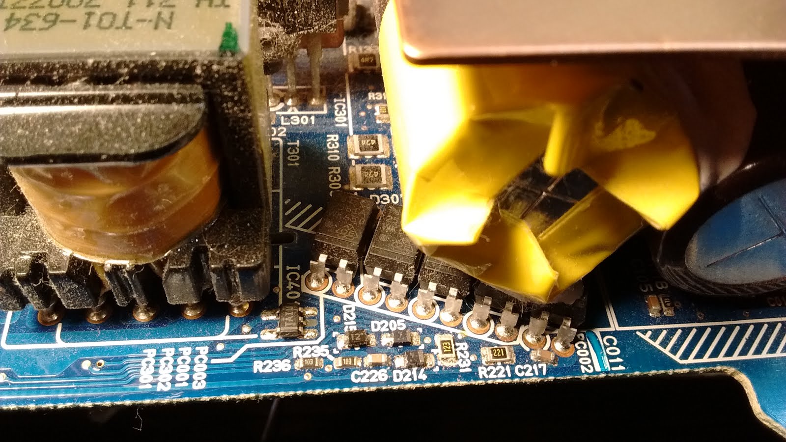
Looking closer at the power supply it has an FCC mark (tested to a standard for RF noise emissions as an unintentional radiator which is required by the US federal code of regulations) and a CE mark on it (Tested to European standards for safety, immunity and RF emissions). However, I was highly suspicious of this. If you look up the official marks for both CE and FCC there are some differences. An image of the assembled and disassembled power supply are attached.

I'm not sure the manufacturer did any safety or EMC testing on it. I work as an Electrical/Electronic Engineer so I had access to some equipment to do a bench test conducted RF emissions scan. I have attached the results and there is no way this power supply/product passes the required test as you can see. The purple line is the upper limit for quasi peak the vertical axis is in dB.  The yellow line is the scan of the peak emissions from the power supply under full load. The limit lines are based on CISPR-14 since that was a previous test I was doing but the lines are about the same for FCC part 15 class B devices which are marketed to residential consumers.
This device with this power supply should not be sold. As you can see from the attached photos there is absolutely no input filtering on this power supply. It's also very likely it has never been tested to any safety standard like UL or ETL. There is no UL or ETL mark on it. These third-party US safety compliance bodies should be used to test products anytime the product is plugged into a wall or generates heat.

I would recommend the supplier or manufacturer do their homework and use a proper UL or ETL listed power supply for this product. On top of this, request the actual test data to verify the device passes EMC testing to continue selling it.

I purchased a different power supply myself that is UL listed and FCC compliant. I tested it and I no longer have the severe noise. 

Now I have to fix my brother-in-law's Christmas present so it doesn't cause me or others problems.

Buyer beware.


--------


As a side note I had a similar experience a couple years back with data from a Noco brand battery charger. No input EMI filters on their US version. They claimed there was nothing in the US that required EMC compliance of their US product. Their CE version had these filters.

Friday, April 17, 2020

Television interference (TVI) from amateur radio transmitter

Recently, I have been operating a bit more with digital modes. This operation is now overlapping some "prime time" television viewing for other household occupants. Transmitting even at fairly low power levels tends to overload the television receiver and causes the digital channel to break up and freeze.

Our current television setup uses a roof mounted antenna similar to this:


This antenna feeds 3 different receivers through 2 RF splitters.

Any antenna that I am able to use for radio transmission is typically low and close to the dwelling. This makes it very easy to overload any cheap over the air television receiver. It seems that most televisions do not implement adequate filtering on their front end.

The solution to this was to install a high pass filter on the first RF splitter input. Since they were of a nice form factor I purchased a filter online instead of building one. I received a "HPF-54" from amazon. It claims to operate with low insertion loss from 54MHz to 1000MHz (OTA TV frequencies) and significantly attenuate signals below this.

Nice compact filter to go inline with the coax. -AC9LF

Good results were immediately noticeable on install. This little filter did not appear to attenuate normal TV stations but seemed to completely remove any TV receiver picture or audio breakup when transmitting with my radio at power levels of around 30 watts on 40m, 30m, and 20m (tested so far).

As a quick check I did an impedance scan across the HF band to 30MHz with this filter on the analyzer. The filter was fitted with a 75 ohm terminator. Resistance is zero across most of the HF band with a good amount of reactive component depending on frequency.
AC9LF impedance scan of HPF-54

Measuring the center conductor with a DMM shows that it is DC blocking.

I also did a scan of  VHF/UHF with a 50ohm antenna analyzer. The range covered is 137MHz to 1000MHz. There will be some loss in the adapters used as I needed to use a SMA-BNC then BNC-F for this testing. The adapters used don't have very good frequency response themselves. There is also an impedance mismatch as I am testing a 75 ohm system and this analyzer is meant to test 50 ohm systems. However as you can see the VSWR is very low. I would expect 1.5 to be a perfect match in this case due to the impedance mismatch.

With HPF-54 inline. -AC9LF

Without HPF-54 inline. -AC9LF

Now the TV can be used to receive over the air stations at the same time I am playing with radios.  This makes for a more tranquil living area.

Here is a link to the product that I purchased for this post:

Ancable in-Line High Pass Filter Coupler Barrel Adapter 54-1000MHZ 2-Pack by Ancable Direct Learn more: https://www.amazon.com/dp/B074K87HTD/ref=cm_sw_em_r_mt_dp_U_BUCMEb1RY2AY1

If I perform any more significant testing or anything else changes I will report back here.

Monday, February 11, 2019

RFI Generator for RDF Practice

I have been having some issue with HF noise in my neighborhood. I would like to track this down and resolve it. The first thing that I did of course was make sure the noise was not coming from my own house. I did this by powering my HF radio with a battery while cutting power to the main breaker of my house. With the noise still present it seems to be coming from outside.

I think I might know the general area of the noise source from driving around with an HT in AM mode and finding a peak in the noise.

However before further investigation and since I am not very seasoned at radio direction finding I decided to get some practice with an RFI generator.

Information on the device I built can be found here:
http://www.w0qe.com/RF_Interference/simple_rfi_generator.html

I chose an oscillation frequency of 1 MHz. This covers the whole HF band and into lower VHF frequencies. I placed a socket on the board to allow the oscillator to be swapped out for different frequencies.
RFI generator assembly

The plan is to use this source with homebrew antennas directional and otherwise to hone my skill in finding these noise sources. Hopefully, I will be able to quickly and accurately locate real ones.

Snapshot of the RFI generator spectrum

Sunday, February 10, 2019

ARISS (02/08/2019) SSTV Event


I was able to capture some images this weekend sent from the ISS for its SSTV event. For those not familiar with it you can visit http://www.ariss.org/ for more information. My setup was a modest 2 meter mobile rig connected to a simple quarter wave vertical in the attic. I used a program called Mmsstv for decoding.  I have posted some of the images that I have captured below.


 (Updated: 2/16/19, ARISS redo weekend)

Monday, April 2, 2018

Quick and dirty HF "SWR" indicator (resistive bridge)

Getting tired of the time it takes to match to my random end fed wire I did a quick search for simple "SWR" LED indicators. I have seen them before. The basic operation of such an indicator is that as the unknown impedance (the antenna/tuner) approaches the impedance set in the device the LED goes dim and if the circuit is completely balance it should go out.

This past weekend I decided to put together one of these circuits with a bypass switch that would allow me to disconnect the resistive bridge. With this type of device you can not leave the circuit in line and you must use low power as the resistors, at least the ones I put in are low wattage.  Mine were parallel 150 ohm 1/4 watt resistors. This gives me a resistive bridge based on 75 ohms. I chose this since this is the impedance of the feed line I use for my HF station (RG6).

I built this circuit into (You guessed it!) an altoids tin:

http://qrpkits.com/images/swr_ind1.jpg

Below are some images of the build:
AC9LF

AC9LF

AC9LF

AC9LF

AC9LF

The switch is a simple toggle switch from an old PC power supply. This allows me to bypass the resistive bridge while still leaving the device connected. This speeds up the process of changing frequency and "retuning" my random wire.

The auto transformer is on a toroid core. This steps up the voltage and allows the LED to light up even at smaller bridge imbalances.

Now, the toroid core I used for the auto transformer was pulled more or less at random from my junk bin. As luck would have it, it actually had a part number listed on it. I looked it up after I built it. It is a powder core from "Magnetics" with a part number: 55848A2. From technical data list on the manufacturers web site this core is really only good to 2MHz. Beyond that the permeability degrades by about 5% every 2MHz. With some testing this weekend it proved useful up to about 20meters. I tried it on 21MHz but the non-lit area on my tuner was pretty wide.

Let me explain how I tested this. I have a L-match attached to an end fed wire. This device is in line between the coax from the radio and the L-match network. I would supply a 1 or 2 watt carrier at the frequency of interest into the setup. I would then adjust the L-match while watching the LED. I would get a very good dim led (almost extinguished) on 40 meters (7.2MHz) and 20 meters (14.2MHz). After checking actual SWR at the radio this presented itself as slightly less then 1.5:1 on a 50ohm SWR meter. A very good result!

My tuner allows matching up to about 21MHz, I tried this but the area that was not lit by the LED on the tuner was pretty wide. Indicating that I will need a bit more power to the device at higher frequencies.

For a good write up please see the link in the SWR meter I posted a long while back. I will try and post a video of this cool little thing in action at some point.

I am pretty happy with this solution as it was dirt cheap, works fast and is very effective. It can be improved on with a better core and some tighter wire routing.

73,
AC9LF

Sunday, January 21, 2018

Repurpose a PS3 Power Supply (32Amp rated)


I was asked to take a look at a Kenwood TS-140s for someone. I was told the radio was acting strange with regard to output power. I did not have a power source available to test this rig as it requires at least a 20 Amp power supply. I thought that I could use my SLA battery mentioned in a previous post but the voltage dropped too low with the massive drain from the radio. I stumbled on an old PS3 power supply I had in my junk bin. The supply claimed 32Amps at 12volts. I set off to use this to test the radio using what I found. I had an old power supply chassis laying around which had questionable panel meters. Spontaneous construction resulted.

PS3 stamped information. -AC9LF

The current meter works fine but the voltage meter needed some TLC. I had to take it apart as the bolts for connection were loose inside of the meter. I also added a series variable resistor because the voltage readings were off considerably. For example 12Volts at the panel showed almost 20Volts on the meter. I was able to make it reasonably accurate with the series resistance. The potentiometer was secured with generous hot glue.

Potentiometer was attached here. -AC9LF


Anyway, the power supply requires that the 5V pin on one side of the connector be connected to the standby pin on the on the other side to turn it on. This is simple enough. I added a toggle switch on the front of the chassis to take the power supply out of standby or put it into standby. A resistor is in series as shown below.


Connector to enable the power supply. -AC9LF

I added a computer fan to the bottom of the chassis to get some air flow past the power supply. I may or may not connect in parallel the capacitor shown in the picture. It is 10,000uF 25V. I don't know how the power supply would respond to such an initial load. You can see I had the IEC power connector/switch put inside the unit. I do not have an ability to cut holes for something like this.

Inside the chassis. -AC9LF
I wired everything up and tested the radio. It worked. There is some switching noise when the antenna is connected about every 100KHz but I was able to transmit using the TS-140s to verify output power. The issue, I think, with the radio is that the slider potentiometers get flaky. Adjusting these on the radio was not smooth. If you move the slider a little it makes a big change or no change. I cleaned them with some contact cleaner and they seem better. The rig puts out a full power into my dummy load and dipole antenna. 

76Vrms into 50ohms, roughly 115 watts. -AC9LF


Back to the power supply. The power supply is hard set to 12Vdc and this works okay but most radios expect something more like 13.8V for operation. I set out to modify the power supply to do this. I cracked open the unit and looked for the feed back circuit. It was a string of opto-couples.

Topside view of the power supply. -AC9LF

Opto-couple feedback area. -AC9LF
The opto-couplers serve various purposes, one is for over voltage protection, one is for 5volts feedback, another for 12V feedback, etc. Figuring out what's what took a bit of time. D215 goes to the over voltage protection feedback and this was modified to allow for a higher over voltage value without disabling the protection completely. The center opto-couple is the feedback for the 12V line. Breaking this connection on pin one, I inserted a 10k potentiometer to vary the current through the device. This allowed for adjustment of the output voltage. As resistance increases voltage increases. Once the over voltage point is hit the power supply shuts down and needs to be unplugged and plugged back in to reset it.

Mod wires to feedback IC. -AC9LF

In place of D215 I added my own 12V Zener Diode and series LED for over voltage protection. The voltage drop across these plus the circuitry still on the board determines the over voltage set point. This causes the power supply to trip on an over voltage at about 15VDC.

Increased over voltage protection mod. -AC9LF

One thing I have to learn over and over is that I should test everything before I close up the box. I had to take apart the chassis twice because I had the power switch off the first time and the second the ac power wire was not connected to the power supply. Ugh... I added the potentiometer to the front panel to adjust voltage if I need to. The potentiometer is on the left ,the standby switch is center bottom and the output terminals are of the banana type on the right. The current meter is the right one and the voltage meter the left.
Power supply on and producing 13.8Volts. -AC9LF
This took a little while to do but I gave scrap electronics purpose again. This was mostly to test the rig I was given to look at but then turned into an experiment to see if I can adjust the voltage of this fixed PS3 supply and utilize it in my hobby. 

There are hazardous voltages inside of this power supply I would not recommend anyone tinker with something like this unless they know what they are doing.

Thursday, January 18, 2018

Repair of two 13.8V 10A power supplies (ICT12012-10AX)

Just last week I took a look at a couple of bad power supplies that I received. Along with a pair of channelized UHF radios. The two power supplies were of the same make and model. Make: "Innovative Circuit Technology Ltd." Model: "ICT12012-10AX" They had different symptoms. One would power up but after a minute or two the voltage would drop off and the radio would shutdown. It also would not supply necessary transmit current. The second had zero output on the 13.8V line, apparently dead.

I took a look at both and decided to start with the first one that had some output. I measured the AC ripple on the 13.8V line and it was showing on my DMM around 300mv rms. The spec for the power supply claimed no more then 25mv of ripple. With that I suspected the output electrolytic capacitors. This is a typical failure with switching power supplies. They require very low ESR (equivalent series resistance) at fairly high capacitance out of the output capacitors. I replaced these capacitors and the UHF radio remained on indefinitely. However on attempting to transmit the extra current draw caused the radio to shut off as the voltage dropped too low. In this case I decided to swap out the remaining capacitors on the power supply including the electrolytics on the primary side. This made the first power supply fully functional.

The second power supply having no output I at first suspected a failed semiconductor. The fuse was fine but I still checked diodes and the main switching transistor with a DMM for shorts across semiconductor junctions . There were none that I could find. With an O'scope, 100x probe and an isolation transformer I checked the main switching transistor for any switching action. There was none. I then looked up the datasheet for the IC that should be controlling this transistor and verified power to the supply pins and checked for switching on the transistor control pin. The voltages seemed reasonable per the data sheet however there was no switching/pulsing occurring at the transistor control pin. After some poking around the power supply came to life briefly with some audible whining. I found that the switching action was intermittent, not consistent. I decided to swap out the capacitors on this power supply as well. Just to be on the safe side I touched up any solder joints on the board that may have been questionable.

The main switching IC has it's own voltage supply on the mains input side. It is made up of simple discreet components providing only enough power for the control circuitry. If the main switching IC is not getting decent power itself as in there is considerable ripple on it's supply line then the power supply may not function properly. A bad capacitor could cause this. After replacing all of the same capacitors that I did on the first unit the second one came to life. The switching was consistent at 100khz without the sharp edges typical of cheap switching power supplies that can cause RFI. This is likely why it is used as a communications power supply.

As a side note, removing the power supply PCB from the chassis required cutting or desoldering the wires going to the output terminal.

Below is an image of the power supply with some descriptors (if you can see them,,,). Circled in green are the capacitors that were replaced in both units. Near the transformer I had to series two capacitors to get the voltage rating that was on the original.

Repaired 13.8V 10A power supply. -AC9LF

The copyright printed on the PCB shows 1997 so these supplies are around 20 years old now. Maybe they will last another 20 or more.

With these power supplies in working order my home PC of 12 years stopped booting up last Friday. That will be another post.

Tuesday, January 16, 2018

Battery Tender and RFI

I have a battery tender paired up with a 12Ah SLA battery. I found that when the unit is plugged in and charging the battery, it generates a lot of RFI up through VHF. When powered up the unit creates full scale interference on my 2 meter station. I like to use this battery on my QRP/experimental radios as it lets me go outside away from outlets. Keeping the battery topped off is important. Unplugging it anytime I want some peace and quiet on the RF spectrum is a bit inconvenient.

Pondering on possible solutions for this I came up with stuffing the whole setup into a metal box and adding additional filtering on the AC input. This keeps it quiet when everything is sealed and it is just maintaining the battery. I had an ammo can that I have just used as a storage box in the past. I modified this with a few holes to mount an EMI filter and allow the power cord to come through the case. I did not have a grommet for the power cord so I applied a liberal amount of hot glue for support and to prevent chafing.
New battery tender setup. Nice and quiet. -AC9LF

The negative side of the battery is bonded to the metal ammo can along with the ground connection on the 3 wire 120VAC plug. The lid is also bonded with wire, star washers and bolts to the main case. This is to make sure there is a good electrical connection. I did not want to rely on the hinge for a connection. I no longer see noise emissions from it on my s-meter in the 2 meter rig. 

The somewhat haphazard insides. -AC9LF

If I use this as a power supply with the charger/tender plugged in it will still generate a lot of hash in the radio. This may be due in part to the lid not being sealed when using the DC connection. I did not route this wire through the case. I was hoping that I might be able to use this as an "automatic backup" power supply for my 2 meter base station. I may be able to remove the conducted noise with more filtering at the DC side of the battery tender.

For now I can keep the battery topped off without the interference normally caused by this thing. I can still unplug it to use the battery. As a bonus it features a nice handle and carrying case for the battery!


The Beach 40 Chassis Transplant

Over the weekend I spent a bit of time carefully moving the innards of the double side band transceiver I built and place them into something a little more suitable. It was originally a plastice enclosure I found. The new enclosure will be a nice round cookie tin. This cookie tin should provide a decent amount of shielding against nearby interference. Especially since most of the gain is in the audio stage and is likely to pick up all manner of things nearby without it.

The cookie tin is a "Benton's Danish Butter Cookies" item that I bought for this purpose and maybe partially for the cookies. I like cookies. I bought it at the store Aldi. The container takes solder very well just as the Altoids containers do. I have not put labels on it yet and at the time I tried testing the receiver again the band was in poor shape due to an active geomagnetic field.

I have had some trouble nulling out the carrier completely with my mixer circuit. I will look into this more but I think it is fairly sufficient for where it is at right now. 

For a future project I am considering building a simple interface to try digital modes with this. It should be fairly straight forward to do. 

Below you will find a picture of the almost finished transplant:

Cookie Tin Radio. -AC9LF

Here's a quick video of the radio receiving a contest station:


Again, a special thanks goes to VK3YE, Peter for the Beach 40 and his videos.

Acquired J-Pole construction skills carried over into home repairs


Not really electronics or ham radio related, well maybe a little... About 6 months ago I went into the basement and found this:


I thought that my water heater failed and was leaking all over the place. However, upon further inspection it turned out that there was a leak but not from the heater tank. The leak was occurring on the hot water side pipe. It was a pin hole leak from the pipe itself not anywhere near a solder joint. A pin hole right through the copper. I attempted to temporarily fix it with a hardware store clamp. This was successful to a limited extent but required much finagling.


Having at the time just soldered together a copper pipe J-pole I acquired rudimentary skills at soldering together this large metal tube. I decided to try my hand at replacing a section of pipe with this leak. The point of no return was the first cut with the tool I purchased for the J-pole experiment. 


The repair was a complete success! As proud as I am of my accomplishment, it does not look the best. The repair has held and seems to be a permanent fix. I just hope this was a fluke and that pin hole leaks will not appear elsewhere in the future.