I was asked to take a look at a Kenwood TS-140s for someone. I was told the radio was acting strange with regard to output power. I did not have a power source available to test this rig as it requires at least a 20 Amp power supply. I thought that I could use my SLA battery mentioned in a previous post but the voltage dropped too low with the massive drain from the radio. I stumbled on an old PS3 power supply I had in my junk bin. The supply claimed 32Amps at 12volts. I set off to use this to test the radio using what I found. I had an old power supply chassis laying around which had questionable panel meters. Spontaneous construction resulted.
 |
| PS3 stamped information. -AC9LF |
 | |
| Potentiometer was attached here. -AC9LF |
Anyway, the power supply requires that the 5V pin on one side of the connector be connected to the standby pin on the on the other side to turn it on. This is simple enough. I added a toggle switch on the front of the chassis to take the power supply out of standby or put it into standby. A resistor is in series as shown below.
 | |
| Connector to enable the power supply. -AC9LF |
I added a computer fan to the bottom of the chassis to get some air flow past the power supply. I may or may not connect in parallel the capacitor shown in the picture. It is 10,000uF 25V. I don't know how the power supply would respond to such an initial load. You can see I had the IEC power connector/switch put inside the unit. I do not have an ability to cut holes for something like this.
 |
| Inside the chassis. -AC9LF |
I wired everything up and tested the radio. It worked. There is some switching noise when the antenna is connected about every 100KHz but I was able to transmit using the TS-140s to verify output power. The issue, I think, with the radio is that the slider potentiometers get flaky. Adjusting these on the radio was not smooth. If you move the slider a little it makes a big change or no change. I cleaned them with some contact cleaner and they seem better. The rig puts out a full power into my dummy load and dipole antenna.
 |
| 76Vrms into 50ohms, roughly 115 watts. -AC9LF |
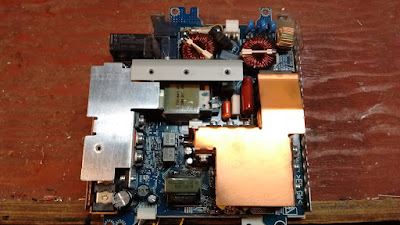
Back to the power supply. The power supply is hard set to 12Vdc and this works okay but most radios expect something more like 13.8V for operation. I set out to modify the power supply to do this. I cracked open the unit and looked for the feed back circuit. It was a string of opto-couples.
 |
| Topside view of the power supply. -AC9LF |
 |
| Opto-couple feedback area. -AC9LF |
The opto-couplers serve various purposes, one is for over voltage protection, one is for 5volts feedback, another for 12V feedback, etc. Figuring out what's what took a bit of time. D215 goes to the over voltage protection feedback and this was modified to allow for a higher over voltage value without disabling the protection completely. The center opto-couple is the feedback for the 12V line. Breaking this connection on pin one, I inserted a 10k potentiometer to vary the current through the device. This allowed for adjustment of the output voltage. As resistance increases voltage increases. Once the over voltage point is hit the power supply shuts down and needs to be unplugged and plugged back in to reset it.
 |
| Mod wires to feedback IC. -AC9LF |
In place of D215 I added my own 12V Zener Diode and series LED for over voltage protection. The voltage drop across these plus the circuitry still on the board determines the over voltage set point. This causes the power supply to trip on an over voltage at about 15VDC.
 |
| Increased over voltage protection mod. -AC9LF |
One thing I have to learn over and over is that I should test everything before I close up the box. I had to take apart the chassis twice because I had the power switch off the first time and the second the ac power wire was not connected to the power supply. Ugh... I added the potentiometer to the front panel to adjust voltage if I need to. The potentiometer is on the left ,the standby switch is center bottom and the output terminals are of the banana type on the right. The current meter is the right one and the voltage meter the left.
 |
| Power supply on and producing 13.8Volts. -AC9LF |
This took a little while to do but I gave scrap electronics purpose again. This was mostly to test the rig I was given to look at but then turned into an experiment to see if I can adjust the voltage of this fixed PS3 supply and utilize it in my hobby.
There are hazardous voltages inside of this power supply I would not recommend anyone tinker with something like this unless they know what they are doing.
Can it modified until 24v? I was change the capacitor to 50v.
ReplyDelete